Outersheath
The plastic coating on the armouring is known as outer sheath. It must have:
• |
Better abrasion resistance |
• |
Better weatherproof properties.It must be stable against ultraviolet rayswhich are in ample in sun light in tropical countries like ours |
• |
Better chemical and oil resistance |
• |
Better fire resistance |
• |
Reasonable price |
Considering the above the most acceptable material for outer sheath is PVC compound. It has good fire resistance due to its chlorine content. It burns when the flame is applied but fire gets extinguished immediately on removal of flame.Fire resistance of plastics is expressed by their Oxygen Index. Oxygen Index indicates the percentage of Oxygen required in air, so that the plastic will burn like a candle at room temperature. The Oxygen Index of normal PVC used in cable is 25 % while that of Polyethylene is 19%. Oxygen Index decreases with the rise in temperature and at a particular temperature it will drop to 20% and will burn like acandle. This temperature in degrees celsius is known as Temperature Index. Temperature Index of PVC in cable is 250C.
Over the year the size of Petrochemical, chemical and Power plants has increased tremendously. Moreover the automation has also increased. As a result now many cables are bunched in the cable shafts and on the cable trays. In case of a fire in these cables, the fire becomes self-sustaining. Moreover due to burning of PVC a dense corrosive smoke is emitted which makes fire fighting difficult due to poor visibility and toxic nature of the smoke. The HCL content of smoke not only damages other nearby costly equipment but also penetrates the RCC structure and corrodes its steel reinforcement Due to this, there is an extensive damage to the human life and property.
To overcome these deficiencies of PVC sheath, FR ( Fire Retardant) PVC compound having a minimum Oxygen Index of 29% was developed, by adding Antimony Trioxide at compounding stage. FR PVC is preferred in Petroleum and Petro Chemical Plants which are open to the sky. FRLS (Fire Retardant Low Smoke) PVC compound is a further development where Aluminium Trihydrate (ATH) and some chemical are added at the compounding stage to increase the Fire Resistance of the PVC and to decrease the smoke emission and toxicity of smoke. But again this is a PVC compound and hence toxic black smoke can not be eliminated completely.
Zero Halogen Fire Retardant (ZHFR) Compound
As discussed above, PVC has got better fire resistance due to its Chlorine (Halogen) Content but it creates other problems during fire. To overcome these deficiencies ZHFR compounds were developed. Here Polyethylene or Ethylene Vinyl Acetate (EVA) plastics which are having zero halogen are imparted fire resistance properties by compounding them with certain chemicals. These materials when burn, emit little non toxic smoke. This is the most preferred sheathing compound for under ground Metros, Stations, Airports, Theatres, Hospitals etc where human density is more.
Polyethylene Outersheath
Due to poor abrasion and fire resistance Polyethylene sheaths are generally not used. Moreover minimum 2.5 % carbon black is required in Polyethylene to prevent its degradation due to ultra violet rays when exposed to sunlight. It is mainly used where better chemical and water resistance are required.
Nylon & Polyurethene Sheaths
These plastics have better abrasion resistance and are used when there are specific requirements.
Rodent And Termiteproof Compound
Some customers specify rodent and termite proof compound for sheathing. According to us there is no such plastics.Moreover there are no rodent and termite repellant chemicals which can be added to sheathing compound to impart the above properties. We have also not come across any test procedure to check the above properties.Poison is extensively used to control the rodent menace and all PVC compounds contain Lead based chemicals added as stabilizers. The attacking rodents may die after consuming PVC but by that time the cable sheath is already damaged by them
Colour Of Outersheath
By default it is black as it imparts weatherproof properties. In case of cables used for intrinsically safe systems blue sheath is provided: Sometimes the clients specify Grey or Red sheath to differentiate the instrumentation cables from the normal Power cablesThe thermocouple Extension cables and compensating cables have different sheath colour to indicate their type .Le Thermocouple Extension cable for type K thermocouple will have yellow sheath and for type J black sheath as per American specification.
Shieled Cores and Paired Cables for PLC and DCS
There is no ISI specification for this type of cables. Generally everybody follows British Specifications asunder:
1) B.S. 5308 (Part 1 ) Specification For Polyethylene Insulated Instrumentation Cables
2) B.S. 5308 (Part 2) Specification For PVC Insulated Instrumentation Cables
These specifications cover cables with Alu-Polyester tape with tinned copper drain wire as shielding Many clients specify I.S. 1554 (Part 1) for this type of cable. This I.S. specification is for heavy duty power and control cables and specifies higher insulation thickness and bigger sized armour wire. Due to this the cable diameter increases and so the cost of cable. Moreover I.S. 1554 does not cover conductor sizes below 1.5 sq.mm Le 0.50, 0.75 and 1.0 sq.mm which are used in instrumentation cables.
Core And Pair Contruction
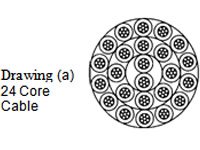
There is confusion in specifying the cable required. If you ask for 24 Core X 1.50 sq.mm cable, we take 2 cores and twist them in one direction, above that 8 cores are laid in opposite direction and above that 14 cores are laid and it looks as drawing (a) below.
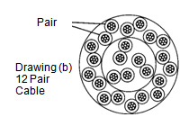
If you specify 12 Pair cable, first we take 2 cores and twist them to form a pair, 3 such pairs are again laid up, above that 9 such pairs are laid up to form a 12 pair cable and it look as drawing (b) below:
The diameter of multi paired cable is always more than that of multicore core cable having the same number of insulated cores and hence multi pair construction is always costlier.
NOTE: One Pair and Two Core cables are same
Identification Of Cores In Core Contruction
B.S. specification specifies all cores yellow and identified with printed numbers and written word in black e.g. Core 10 would be coloured yellow and identified by number 10- TEN in black.We provide different colours up to 6 cores, and there after one blue, one yellow and remaining grey in each layer with number printing in black e.g in case of 12 core cables the 1 st innermost layer will have one blue, one yellow and one grey cores with number 1 ,2,3 printed on them respectively. The 2nd layerwill have one blue, one yellow and 7 grey cores with number 4,5,6............. printed on them respectively. In this case if the numbers are not legible the cores can be identified by counting the cores Le blue, yellow, 1stgrey like that.B.S. specification specifies the following colour code for paired cables.
PAIR NO. |
A-CORE |
B-CORE |
PAIR NO. |
A-CORE |
B-CORE |
01 |
WHITE |
BLUE |
11 |
BLACK |
BLUE |
02 |
WHITE |
ORANGE |
12 |
BLACK |
ORANGE |
03 |
WHITE |
GREEN |
13 |
BLACK |
GREEN |
04 |
WHITE |
BROWN |
14 |
BLACK |
BROWN |
05 |
WHITE |
GREY |
15 |
BLACK |
GREY |
06 |
RED |
BLUE |
16 |
YELLOW |
BLUE |
07 |
RED |
ORANGE |
17 |
YELLOW |
ORANGE |
08 |
RED |
GREEN |
18 |
YELLOW |
GREEN |
09 |
RED |
BROWN |
19 |
YELLOW |
BROWN |
10 |
RED |
GREY |
20 |
YELLOW |
GREY |
ITO (Indian Telephone Oept) also specifies the above code.
Sometimes the clients specify red-black,white-blue,white-:black,blue-brown with number printing for multipair cable. We believe that the colour identification is a better identification as compared to number printing. Moreover in case Polyethylene insulated cables the bonding of printing ink with Polyethylene is very poor and the printing gets erased easily. To avoid this the Polyethylene insulated cores must be treated with Corona before printing .Nowadays the cable manufacturers use computerized black ink printing machine for number printing and here the print on dark surface is not clearly visible. Frequent changing the colour of ink or to use pigmented ink Le. White in these machines are very difficult and hence we request the clients to choose light colour like White-Blue, White-Yellow, Red-Blue as base colour for multi pair cable.
Pair Contruction
Two insulated conductors is uniformly twisted together to form a pair. The lay of length used is such that the two cores forming the pair are not dissociated by normal handling. As discussed earlier, close twisting is more effective in combating Electromagnetic interference. Too close twisting creates problem in processing and hence 10 twists per meter is generally adopted by the industry and it is in line with B.S.5308 requirements.
Telephone Pair
Sometimes on the request of the client a telephone pair of 0.50 sq.mm size is incorporated in multi pair cables. To this a telephone is connected at the time of termination of cables, for communications between persons working at two places which are far off.